Trap Antenna Design Calculator
Trap antenna works:
TRAP is like an electronic switch. We know that many antennas can effectively resonate and work in more than one band, one of which is called a Trap antenna. Trap is a combination of an inductor and a capacitor, usually connected in parallel by an inductor and a capacitor. When the frequency of the electric wave is equal to the resonant frequency of the parallel circuit, the circuit exhibits a high impedance and can be regarded as an open circuit; if the frequency of the electric wave is lower than the resonant frequency, the circuit is inductive; and when the frequency of the electric wave is higher than the resonant frequency, then Conformal.
Trap antenna calculation tool
Many antennas can effectively resonate and operate in more than one band, one of which is called a Trap antenna.
Trap is a combination of an inductor and a capacitor, usually connected in parallel by an inductor and a capacitor.
When the frequency of the electric wave is equal to the resonant frequency of the parallel circuit, the circuit exhibits a high impedance and can be regarded as an open circuit; if the frequency of the electric wave is lower than the resonant frequency, the circuit is inductive; and when the frequency of the electric wave is higher than the resonant frequency, then Conformal.
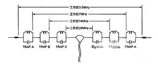 |
| A four-band Trap Dipole |
In the figure, the resonant frequencies of Trap A, B, and C are 7MHz, 14MHz, and 28MHz, respectively, and they are each paired to a specific frequency band. It exhibits high impedance characteristics, while for other frequencies, it exhibits only a small inductive reactance or capacitive reactance.
Thus, in different bands, Trap A, B, and C are like electronic switches, like connecting or disconnecting various parts of the antenna to achieve the effect of automatically changing the length of the antenna. Our homemade Trap antennas work like this.
The electrical length of the antenna is always in resonance with frequency changes.
Another form of Trap, commonly found in commodity antennas, differs slightly from the previous principles. The Trap of such an antenna generally does not resonate in an amateur band, but is outside the amateur band.
When the working amateur frequency is lower than the resonant frequency of the Trap, the Trap is inductive, equivalent to the inductance applied to the antenna, and has the effect of extending the electrical length of the antenna; conversely, when the operating frequency is higher than the resonant frequency of the Trap, the Trap is presented. Capacitive, like a capacitor connected in series with the antenna arm, can shorten the electrical length of the antenna. As a result, the physical length of the antenna does not change, and the electrical length changes with the operating frequency to ensure that the antenna is always in resonance.
Trap has such an effect, not only used in vertical antennas, horizontal dipole antennas, but also widely used in multi-band pointing antennas to avoid the problems caused by a pointing antenna in each band.
TRAP can be replaced by transmission line
Trap can also be replaced by a transmission line, a 1/4λ (wavelength) transmission line short-circuited at one end, and a parallel circuit of inductance and capacitance resonating at the corresponding frequency, the effect is exactly the same.
Due to the need for waterproofing and high voltage processing in inductors and capacitors in conventional Traps, transmission line type Traps show their advantages and are often used in commercial multi-band antennas, especially VHF multi-band pointing antennas.
Simple and practical three-band TRAP DIPOLE
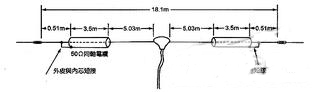 |
| Three-band Linear Trap Dipole designed by G3TKN |
The Trap in the figure is a 1/4 λ transmission line short-circuited at one end.(50ΩCoaxial cable,For example RG- 58/U),The resonant frequency is 14MHz. So between the two Traps, the Dipole works at 14MHz; but for 7MHz, the Trap is inductive. At this time, the entire antenna resonates at the Inductively loaded Dipole at 7MHz; and for the 21MHz Diploid, it can also be used throughout. Resonant operation over the length of the antenna.
It should be added that the two ends of the cable should be properly sealed to protect against moisture; and because Dipole itself increases the extra weight of the cable, it would be better if it is inverted V-shaped.
Both ends of the antenna must be adjusted during actual erection, the so-called Cut and Try; and the power of this antenna should not exceed 250W.
So you are done. Is it easy to make a practical multi-band DIPOLE antenna?